Rigging
[Home]
|
A picture of my Hild asymmetric
spinnaker which I have yet to fly. I need to rig a tack line.. |
|
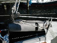
Sorry about this picture of the
boom end. I took it because I intend to put an external 3:1 or 4:1
purchase outhaul. The picture is a reference of the rigging while
I figure out the layout. |

|
This is an Adobe Acrobat file detailing
how to replace the lower shroud eyebolts. File is approximately 450
Kbytes. |

|
This Microsoft Excel spreadsheet provides
suggested rig tension as measured on several boats on the Chesapeake Bay.
This spreadsheet includes suggested rig tension numbers from master
rigger, Brion Toss. |
|
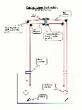
This image shows how to run the
lines from the mast aft to the cockpit. This image courtesy Bob Deuer.
BTW, none of my lines run aft to the cockpit. |
|
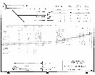
A layout of the Catalina 27 rigging requirements. It lists lengths, diameters, and while type. |
|
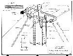
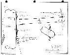
A view of the masthead crane and
rigging. |
|
A schematic of the spreader socket
upgrades. I upgraded my old spreader sockets to the new stainless
steel sockets in the winter of 2001. |
|
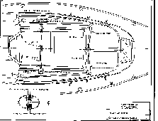
A schematic of the Catalina 27 deck
layout or parts of it. |
|
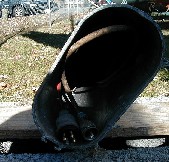
A photo of the mast wiring showing
the VHF antenna wire disconnect and the steaming light/deck light disconnnect
fittings. |

|
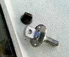
A view of the new lower shroud eyebolt
upgrade. The sealant has squeezed out from beneath the flange and
was easily trimmed away when it cured. |
|
No comparison between the two eyebolts.
The old one is shown prior to removal. Notice the substantial
flange area on the new eyebolt for increased sealant area. Also note
the screw holes that retain the eyebolt from twisting while tightening the
backing nuts. |

|
A view of the original cast aluminum spreader socket. Castings have nasty tendency to crack along large metal grain boundaries often out of sight. |

|
The back of the new stainless steel
spreader socket. I've covered the back with white electrical tape
to form a barrier between the aluminum mast and the stainless socket. This
prevents a galvanic response to set up between the two dissimilar metals.
|

|
The new and old spreader sockets
side-by-side. |

|
A photo of the new stainless sockets
before installation. |
|
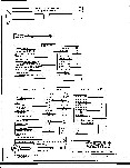
Rigging diagram. |

|
A picture of the rig. I'm
flying two burgees; HHSA club burgee below the State of Maryland flag. |
|
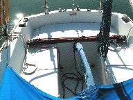
A view of the new traveler upgrade
and cockpit layout. |
|
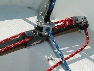
Another view of the new Garhauer
traveler. |
|
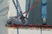
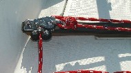
Top view of the Garhauer traveler. |
|
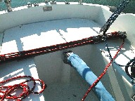
Turning block and cleat for the
traveler line. |
|
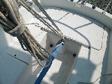
Yet another view -- can you tell
I like this piece of hardware? |
|
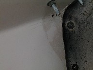
For reference, a view of the old
OEM traveler. It consisted of a piece of sail slide track, two thumbscrews,
and a slider. Dangerous. |
|
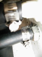
This is an image of the split backstay
chainplate bolts in the lazarette. There are two of them per tang.
This is the port side. |
|
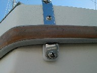
This is an image of one of the starboard
split backstay chainplate bolts in the lazarette. The picture show
a tight fit and close proximity to the holding tank and fuel tank vent hoses
and thru-hulls. |
|
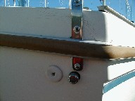
An image of the port backstay chainplate
showing the spacer between the chainplate and the hull and a little of the
groove that was cut into the rub rail. |
|
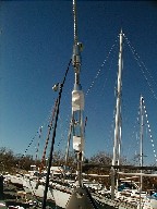
The starboard backstay chainplate
showing close proximity to the holding tank and fuel tank vents. |
|
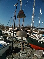
This is an image of the Norse fitting,
the turnbuckle, and the top of the delta plate. |
|
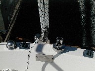
The delta plate, the twin bridles,
the bridle car, and the top of the 4:1 backstay adjuster. The adjuster
is a Schaefer Marine boom vang. All hardware is made by Schaefer Marine. |
|
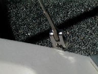
The adjuster attached to the centerline
chainplate were the old single backstay attached. |
|
An image showing the top of the chainplate
and the one of the legs of the bridle. |
Copyright 2001, 2002 Carl G. Schaefer, Jr.